Background (lateral linearization)
“Background (lateral linearization)” allows you to correct for the distant location dependence of the scanner. To correct for the lateral scanner non-linearity, you need to contain a set of EBT film that’s homogeneously exposed to three to seven different dose. The EBT film has to be wide enough to cover the used scanner area width and high enough to have sufficient averaging of all overlaid effects including exposure variations, thick variations of the film and noise of the scanner.
- Double click on “Background (lateral linearization)” then right click on “Data—Background scan #1 (empty)” and select one of the following:
- Select “Open image ‘Background scan #1’ from file” to open an image that contains a blank film (with scanner information) from the computer.
- Select “Scan image ‘Background scan #1’” to scan a blank film to correct for scanner effect.
- Repeat the processes above with the film 180 degree rotated, flipped, and flipped with 180 degree rotated.
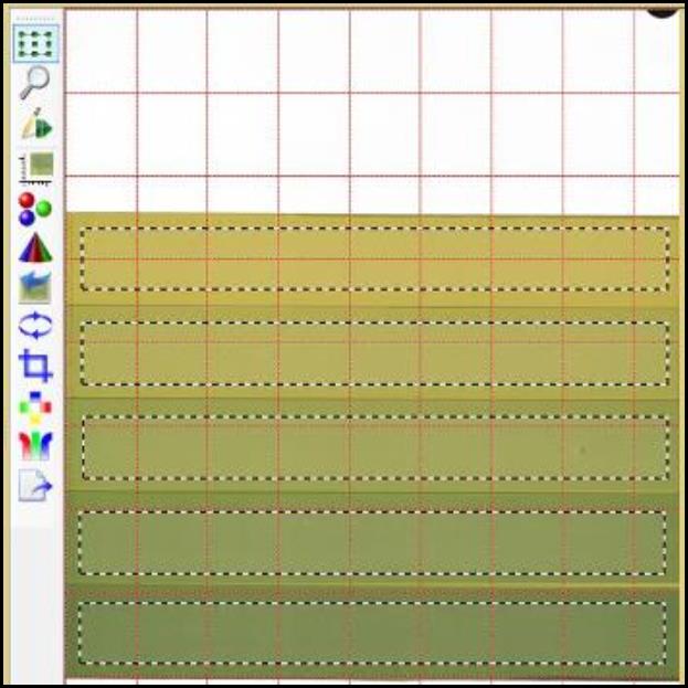
- Under “Image Panel,” create multiple frames, each cover the evenly exposed area.
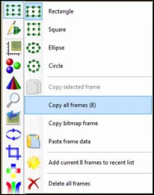
- Under “Image Panel,” click on “Selection frame tool” and select “Copy all frames.” Click on the next “Data – Background scan” and click on “Selection frame tool” again. Select “Paste frame data” to paste all the frames to the background. Repeat for all the scans.
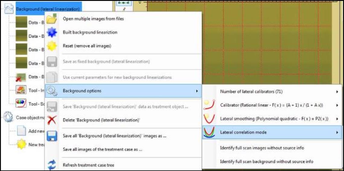
- Right click on “Background (lateral linearization)” and select “Background options” for the method parameters:
- Select “Number of lateral calibrators” to choose the number of discrete lateral positions where data are collected. The number in the parentheses indicates the current parameter selected.
- Select “Calibrator” to choose the function used to correlate color dependence of the scanner function S. See detail descriptions in “Scanner Linearization Panel.” The function in the parentheses indicates the current selected one. Recommend functions are marked with 3-4.bmp.
- Select “Lateral smoothing” to choose the function to smooth lateral color correction function. It is used to correlate lateral dependence of scanned color values at fixed color (value of scanners reference region).
- Select “Lateral correlation mode” to choose the function which allows projecting color channel data in order to make the lateral correction function more “similar.”
- Choose “Correlate each color separately” to correlate color channels independently.
- Choose “Joint correlation at collocation colors” to merge data of all color channels using color channel values of each collocation color channel.
- Choose “Joint correlation at fixed collocation channel value” to merge data of all color channels using channel value of the active collocation color channel.
- Select “Identify full scan images without source info” to accept images without scanner source info for compensation when its pixel size is the same as the full scanner area and scanner and image resolutions are the same. When the option is not selected, images without source info are declined.
- Select “Identify full scan background without source info” to identify background scanner source info by full scan pixel size at background resolution.
- Click on “Tool – Scanner linearization data editor” to open the “Scanner Linearization Panel” on the right side of the screen. Under “Regions Panel,” choose the preferred parameters such as calibrator size and location, reference region size…etc.
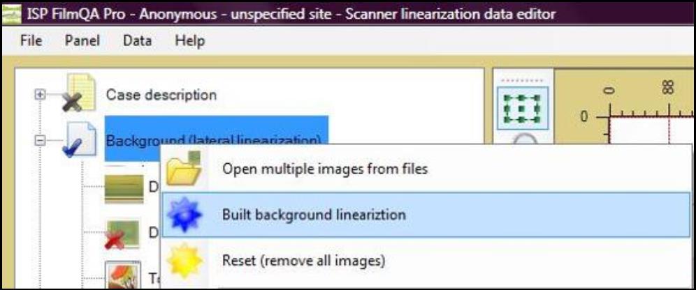
- Right click on “Background (lateral linearization)” and select “Built background linearization.”