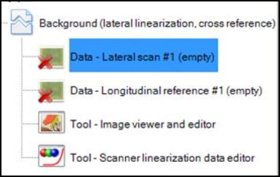
Background (lateral linearization, cross reference)
“Background (lateral linearization, cross reference)” allows you to correct for the non-uniform thickness or unevenly exposed EBT film stripes in addition to the lateral scanner non-linearity.
- Double click on “Background (lateral linearization, cross reference)”
- Select “Data – Lateral scan” and scan the film strips as described under “Background (lateral linearization)” in lateral direction.
- Select “Data – Longitudinal reference” and rescan the EBT film in longitudinal direction multiple times by positioning every single homogeneously exposed area at the center of the scan area.
- Under “Image Panel,” create multiple frames in the lateral scan, each cover the evenly exposed area. Use “Selection frame tool” to copy, paste, and flip the frame from the lateral scan to the longitudinal scans so the region of interest for each test strip is the same.
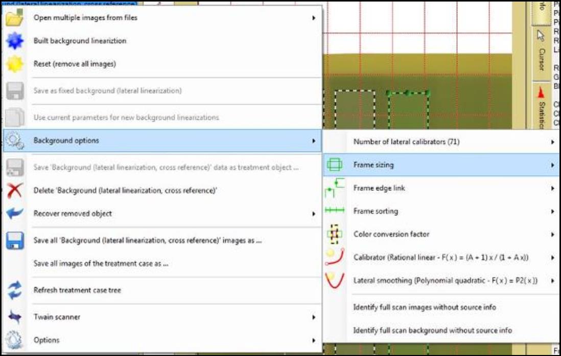
- Right click on “Background (lateral linearization, cross reference)” and select “Background options” for the method parameters:
- “Frame sizing” determines how size variations of lateral and reference region are managed.
- Select “Average of lateral and reference size” to use the average size of both directions relative to center of regions.
- Select “Minimum of lateral and reference size” to use the minimum size of both directions relative to center of regions.
- Select “Manual” to use manual set frames without changes.
- “Frame edge link” determines which frame edge belong to the same test stripe location.
- When “Lateral left, longitudinal top” is selected, the left edge in lateral scan is at the same film position as top edge in longitudinal scan.
- When “Lateral right, longitudinal top” is selected, the right edge in lateral scan is at the same film position as top edge in longitudinal scan.
- “Frame sorting” determines how lateral and longitudinal frames are matched.
- Select “None” to manually set the order of the lateral regions corresponding to the manual set order of the longitudinal regions.
- Select “Total sorting” to sort all the lateral and longitudinal regions by their average color values. ¨
- Select “Blockwise per lateral scan” to have n lateral regions of the first scan matching with the first n longitudinal regions using their average color values.
- “Color conversion factor determines what average value is used to normalize the color values of the longitudinal scans.
- Select “Average of both full frames” use the average size of both directions relative to center of regions.
- Select “Intersection average of lateral and reference region” to use the intersection of lateral region and selected scanner reference regions.
- Click on “Tool – Scanner linearization data editor” to open the “Scanner Linearization Panel” on the right side of the screen. Under “Regions Panel,” choose the preferred parameters such as calibrator size and location, reference region size…etc.
- Right click on “Background (lateral linearization)” and select “Built background linearization.”